

Creative people are designing and building their own custom pieces of hardware, with the filter being amongst the most popular. One of our dBs Institute degree students has built his own hardware filter and shared the design process.
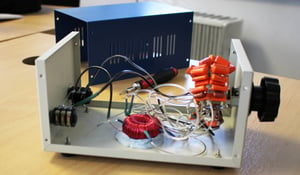
The humble filter can be found in almost any contemporary music set up. From the EQ circuits of classic analogue consoles, to multimode modules in Eurorack synthesisers, filters are used in almost every conceivable audio processing scenario. Here at dBs Institute they are put to good use in all of our courses and students get to use the industry's finest designs throughout their projects. For one of our degree students (Curtis Roberts) a love for the humble filter grew into a passion. This naturally lead to the study of filter design and circuitry, resulting in the creation of his very own high pass filter (image above). With the current surge in DIY electronics for music production, we caught up with Curtis to share his 5 step process for designing a custom hardware filter.
1. Set The Specifications For Your Filter
The first stage in the design process involves setting the requirements you want for your filter. Will it be able to achieve high pass, low pass, band pass, band stop or multimode filtering? If you are designing a high pass filter, for example, you will need to determine what frequencies you want to cut out. Next you will need to consider the filter slope, how will it roll off in db/oct? Setting out your specifications at this early stage and sticking to your plan will help you to pick the right components and design the best type of circuit for your filter. Go here for more information on filter types and slopes.
2. Research The Different Filter Circuit Types
With your specifications set, you can then work out the best filter circuit for the job. This stage involves research. Start by studying filter circuit types and designs and designs for your filter type. A good source of inspiration can be found by studying the schematics of EQ circuits in analogue mixing consoles. Be careful, this could lead to you wanting to recreate 'legendary' filter circuits, such as the PuigTec EQs! Although studying the classics is advised, ask yourself "does this design fit my needs?". Plenty of researching at this stage will be beneficial, when it comes to designing the circuit. You will also start to work out the components you will need for your design and order list later.
3. Design Of The Filter Circuit
Start by drawing out a schematic circuit diagram or maybe following one you've found online. If you need help reading and writing schematics, there's information online that will tell you what the different symbols mean. With this stage complete you are very close to building your filter! Make sure you double check the the schematic to make sure there are no errors. An error at this stage could be costly if you go on to order the wrong part. An incorrect diagram could also lead to short circuits on the finished product.
4. Create The List of Materials
(Electronic hobbyists often refer to this as the BoM - Bill of Materials)
By designing your circuit you should now have a good idea of the materials and components needed to start your build. Create a list of components you need such as resistors, capacitors, switches, pots, jacks etc. These will vary on your requirements such as sliding pots for a graphic EQ or rotary pots for a high pass filter. The specs for your filter (type, frequencies attenuated and db/oct roll off) will determine the component values you need for you resistors capacitors and other parts. In a lowpass filter circuit the combination of a 100 ohm resistor with an 11 microfarad capacitor will have a cutoff of 144Hz whereas if you change the resistance to 250 it'll be a cutoff of around 58Hz.
Here is an example of an RC guitar circuit where the position of the resistors and capacitors determine whether the filter is in a low or high pass style. This example shows a filter with a 6dB per octave roll off, to increase the slope your would need to repeat the same circuit multiple times the trade off is, in a passive circuit you also loose energy each time you do this which equates to a volume drop. Check out the following tutorials 1, 2 & 3 for more information.
You will then need to find an electronics supplier to purchase your components. If you're recreating an existing filter circuit, electronics suppliers sell kits for existing circuits. Using a kit can save time and hassle sourcing individual parts.
5. The Build
To start your build you will need the following tools and equipment:
- A breadboard
- A soldering iron or station
- Wire
- Multimeter
- Your components
- Screwdrivers
- A power supply for active components (it could be a battery).
With your equipment ready and parts delivered you can start putting your filter together. Check against your schematic making sure nothing is wired up incorrectly. Breadboards can be useful to test if the circuit works before you solder it. If you are not confident soldering you should first practice using some cheaper kits/components until you get the hang of it. You may damage your components otherwise. Don't be disheartened if the circuit doesn't work after building it. You will learn more by finding out why it's not working.
FIND OUT MORE